Warms your body and soul: a Swedish stove with oven and stove is the embodiment of comfort. Laying the Buslaev Swedish stove (masonry order) The best Swedish brick stove for the home
A Swedish stove is a warm, cozy home and delicious food. Significant advantages of the stove: small area, less wood consumption, combination of a heating stove and cooking capabilities. We have prepared step-by-step instructions for you with drawings and order so that you can fold it yourself.
Foundation - monolithic concrete
Materials
Concrete grade B15 (M200) is suitable for the foundation for the furnace. To prepare such concrete, the components are taken in the following proportion: cement - 1 part, crushed stone - 4 parts, sand - 2 parts.
Cement must be taken at least M400. The coarse aggregate can be crushed stone or gravel, the particle size of which does not exceed 30 mm. Sand with impurities of no more than 10% is suitable for concrete work. These include clay, mica, organic origin and dust particles. Impurities in coarse aggregate should be less than 2%.
The required materials for the foundation can be calculated based on the consumption per 1 m 3 of ready-made concrete:
- Cement M400 - 325 kg/m 3.
- Sand - 1300 kg/m3.
- Gravel (crushed stone) - 1300 kg/m3.
- Water - 205 l/m3.
Tools
To carry out concrete work, you must have a tool with which:
- lay the concrete mixture (shovel, trowel);
- compact (tampers, probe);
- smooth (ironing board, trowel, grout, iron, corner).
 1 - dipstick; 2 — narrow tamper; 3 - round tamper; 4 — square tamper; 5 - ironing board; 6 - scraper; 7 - half grater; 8 — ironing board
Sequence of concreting
It is very important to determine the depth to which you need to lay the foundation for the stove. This depends on the ability of the soil to resist loads on it (bearing capacity). There are quite a lot of soils with weak bearing capacity. Under the influence of loads, they can change their original structure (subsiding loess and containing soluble salts, swelling clay, of biological origin, as well as water-saturated, increasing in volume in winter).
So, for example, for fine (silty) sands, sandy loams, loams and clays, in which groundwater is located above the depth of soil freezing, the bottom of the foundation is assigned below this level. The depth of freezing is determined based on the results of long-term observations.
 1 - sand cushion; 2 - gravel; 3 — freezing depth; 4 - monolithic foundation; 5 - waterproofing; 6 — floor level; 7 - brickwork
This is the case if the house may not be heated in winter. If the house is heated throughout the winter, then the base of the foundation should be at a depth of more than 50 cm from the layout of the land plot.
In dense soils with good bearing capacity, the foundation can be concreted without formwork. Then a hole is dug exactly according to the size of the foundation. If the soil crumbles, formwork is necessary. It is made from coniferous or deciduous wood, which is not subject to warping. The boards are taken with a thickness of at least 19 mm and a moisture content of no more than 25%.
At the bottom of the hole under the foundation, a cushion at least 15-20 cm thick is made of sand and gravel, which is compacted.
When laying the concrete mixture, be sure to tamp or compact it to release any air bubbles that appear in it. This increases the density of concrete, and therefore strength.
Caring for freshly laid concrete consists of maintaining the required temperature and humidity. This is protection against rapid drying of the concrete surface in windy, hot weather using some kind of wet covering (burlap, tarpaulin, wet sawdust or sand).

Protection of fresh concrete from excessive moisture, drying, and cooling is carried out for one to two weeks in accordance with the outside air temperature. The most important thing is that the concrete gains at least half of its full strength.
The formwork can be removed only when sufficient concrete strength (50%) has been achieved. Most often, this occurs no earlier than 7-14 days at temperatures from +5 to +20 °C. The higher the temperature, the faster the strength gains.
Waterproofing (2 layers of roofing material) is placed on top of the hardened concrete. The size of the foundation should be taken 100 mm larger at each edge of the furnace.
Sequence of construction of a Swedish-type furnace
Materials
For stove masonry, you need a brick that will withstand high temperatures. These include ordinary clay bricks (GOST 390-96) and refractory fireclay bricks (GOST 530-2012).
Important! For kiln work, the use of silicate, hollow, unburnt, or cracked bricks is unacceptable.
In total, for a Swedish-type stove, excluding pipes, you need:
- Clay bricks - 505 pcs.
- Fireproof bricks - 25 pcs.

The furnace can be laid using clay-sand mortar, or a ready-made fire-resistant mortar for furnace work. Today, stores offer several types of such solutions.
A clay-sand solution can be prepared based on the following proportion for clay of different fat contents:
- Oily clay (2-4% sand) - 1 part clay: 2.5 parts sand.
- Medium clay (15% sand) - 1 part clay: 1.5 parts sand.
- Skinny clay (30% sand) - 1:1.
To prepare the solution, the clay is first soaked for 24 hours, then sand is gradually added to it in portions, constantly stirring until smooth. Water is also added in portions. Finally, you need to add water immediately before work. The clay solution should slide off the shovel easily, without spreading.
Furnace appliances
- Blower door (140x140 mm) - 1 pc.
- Fire door (210x250 mm) - 1 pc.
- Cleaning door - 5 pcs.
- Gate valve with hole (120x210 mm) - 1 pc.
- Oven (300x365x450 mm) - 1 pc.
- Plate (410x710 mm) - 1 pc.
- Grate – 1 pc.
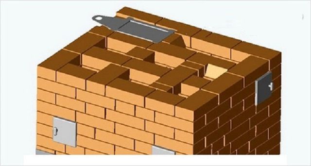
- Metal sheet (750x500 mm) - 1 pc.

The oven can be made from sheet steel by welding. For protection, the outer surface is coated with fire-resistant enamels or varnishes.
Directly under the firebox a metal sheet (750x500 mm) is laid on asbestos cement.
Tools for laying a furnace
 1 - pickaxe; 2 - various trowels; 3 - jointing; 4 — level; 5 - square; 6 - mallet; 7 - plumb line
The firebox and smoke circulation (chimney) are the main parts of the stove body. Fuel is burned in the firebox. Smoke circulation increases the internal surface of the stove, accumulating heat in its mass, and transferring it to the heated room.
 External view of the oven: 1 - cleaning doors; 2 — blower door; 3 - combustion door; 4 — oven; 5 - hob; 6 - valve
A grate is installed in the bottom of the firebox to provide air access to the fire. To ensure a normal combustion process, the draft in the furnace is regulated by a certain position of the combustion and ash doors. The heat output of the Shvedka stove in question is 3200 kcal/hour. It includes a cooking chamber and an oven.
It is necessary to begin furnace work only if there is a covering over the intended location of the furnace, at least temporarily. It is advisable to first make a selection of bricks for each row, combing them and tying them dry.
Orders
Before starting masonry, it is necessary to check all the dimensions of the foundation and determine the orientation of the furnace, including where the pipe will pass through the ceiling, as well as the roof. Immediately before work, ordinary clay bricks are soaked for 2 minutes, and fireclay bricks are only rinsed.
The first and second rows are laid with seams bandaged at least 1/2 brick. For masonry with ordinary clay bricks, a joint of less than 5 mm is required. It is allowed in the case of using 3/4 bricks to bandage 1/4 bricks.


Important! The masonry must be carried out while maintaining verticality along the plumb line and horizontality along the level of all seams.
The third and fourth rows form the ash chamber. There are also 3 cleaning doors installed here. They are inserted with a gap of 3-5 mm directly during masonry work. The gap is filled with asbestos cord. The top of the doors should be level with the horizontal joint of the masonry.


In the fifth row, the firebox is laid out with refractory bricks, the thickness of the seam for which should not be more than 3 mm. A grate is also installed here with a gap of 3-5 mm. The grate openings are directed along the firebox. The gap is filled with sand or ash. An oven is also installed in this row. The formation of chimneys begins at the rear of the furnace.

Important! It is not allowed to bind refractory and clay bricks, since they have different expansion rates under the influence of temperature and can contribute to the formation of cracks.
The sixth, seventh, eighth, ninth rows form the combustion chamber. The combustion chamber door is installed with a gap (3-5 mm) filled with asbestos cord. The wire screwed to the door is embedded in the brickwork. Fireclay bricks are placed on edge between the furnace and oven.


The tenth row involves covering the oven. The partition between the oven and the furnace is raised by 1-2 cm. Next, a layer of clay-sand mortar is laid on the oven to the level of the partition. A corner of 1000x40x40 mm is placed on the front side under the slab.

Eleventh row. The hob is laid and then smoke channels are formed.

Twelfth to sixteenth rows. The cooking chamber and chimney channels are formed, taking into account the ligation of the seams.


Seventeenth, eighteenth rows. To cover the cooking chamber, bricks are placed on strip steel and corners. A wire is screwed to them and embedded in the masonry.


Two cleaning doors are installed in the nineteenth and twentieth rows.


The twenty-first to twenty-eighth rows form chimneys according to the order. In the twenty-seventh row, a valve is also installed with a gap (3-5 mm) and sealed with an asbestos cord.


In the twenty-ninth row, the stove masonry is expanded by 5 cm for the cornice. All channels are blocked, except for the pipe.

The thirtieth row suggests an expansion of another 5 cm.

Thirty-first row. The furnace size is reduced to the original size.

Features of pipe laying
Next, a pipe the size of five bricks is laid. Three rows up to the ceiling, pipe fluffing begins to protect the wooden floor structures from hot gases. The thickness of the pipe in this place should be 1.5 bricks. They also increase the thickness of the pipe when passing through wooden roof structures. A metal cap is installed on top of the pipe. The entire outer part of the pipe is laid using cement-sand masonry mortar.


The height of the pipe above the roof is laid out according to the diagram. To increase traction, the height is related to the distance from the roof ridge.

The oven will fill your beloved home with warmth, comfort and kindness!
Brick heating and cooking stoves, the designs of which will be presented below, can be called the best option for installation in country cottages and private houses. The functionality of this variety is such that it allows you to heat the room and feed the whole family a delicious lunch. Equipped with an oven, a drying chamber, and sometimes a water-heating box, heating and cooking stoves are able to create the most comfortable conditions for living in a home without centralized or autonomously arranged amenities.
This type of furnace can have different sizes and design features. Structures can be massive or compact, and, as a rule, the necessary models are selected in accordance with the area of the house. Therefore, it is very important to take into account not only the functional qualities of the heating structure, but also its heat transfer. When choosing a place to build a stove and carry out thermal insulation of a building, it is necessary to take into account the rules of SNiP 41-01-2003 developed by specialists, otherwise problems may arise with organizations that control the fire safety of residential buildings.
When deciding to build a stove yourself, you need to prepare for labor-intensive and quite lengthy work, since the laying process must take place measuredly and carefully. If you have no experience in the skill of a stove maker, you should strictly adhere to the tips and recommendations that will be given below, as well as carefully study and thoroughly analyze the presented ordering diagrams.
Criteria for choosing the design of a heating and cooking furnace
As mentioned above, many designs of heating and cooking stoves with different performance characteristics have been developed. In order for this heating device to be efficient in operation and meet all requirements, it is necessary to pay attention to the following points during its construction:
- Dimensions of the brick structure. When choosing the size of the stove, you need to take into account the fact that its side walls give off more heat than the back and front surfaces.
- Considering the size of the walls and their ability to transfer heat, it is necessary to consider how the stove will be installed. To quickly and efficiently heat a room, the stove is placed with its side facing it, and the cooking chamber is turned towards the kitchen area.
- The shape of the stove can be T-shaped, square, rectangular, and also with a protrusion in the form of a stove or a stove bench. Each of the stoves, when installed correctly, can heat from two to four rooms.
- The heat output of a brick heating structure is selected depending on the area and location of the room that it must heat.
This table shows the dependence of the dimensions of the furnace (the area of its walls) relative to the area and location of the heated room:
| Room area (m²) | Furnace surface (m²) | |||
|---|---|---|---|---|
| Not a corner room, inside the house | Room with one outside corner | Room with two external corners | Hallway | |
| 8 | 1.25 | 1.95 | 2.1 | 3.4 |
| 10 | 1.5 | 2.4 | 2.6 | 4.5 |
| 15 | 2.3 | 3.4 | 3.9 | 6 |
| 20 | 3.2 | 4.2 | 4.6 | - |
| 25 | 4.6 | 6.9 | 7.8 | - |
- For small rooms, you should not choose massive heating structures, since they can be heated by a compact stove. To heat up a massive stove, a large amount of fuel will be required, and such a structure will take quite a long time to warm up.
- The efficiency of the furnace will directly depend on how insulated the building is. In a well-insulated house, a small stove will be sufficient, since the walls, floor and ceiling will reliably retain the heat it generates indoors and will reliably protect against the cold trying to penetrate from the outside.
Only after taking into account all these factors do they make a choice in favor of one or another model of heating and cooking stove.
Models of heating and cooking stoves
The design of multifunctional stove models can be different - either with a complex internal configuration of chimney ducts, or completely simple. If the laying of the stove will be done by a novice craftsman, then you should not immediately “swing” at complex and incomprehensible structures. Before getting down to work, you need to try to figure out how the heated air, along with combustion products, will pass towards the chimney pipe, since during laying it will be necessary to comply with all row configurations in order to remove the gas exhaust channels correctly.
The most popular models that have a design accessible for masonry are “Swedish”, “Dutch” and a hob. In addition to them, there are heating structures that are named after the names of their developers. Thus, you can find the orders of heating and cooking stoves of Proskurin, Bykov, Porfiryev, Kuznetsov, Podgorodnikov and other craftsmen.
You might be interested in information about how .
Ovens can also be divided according to their shape. So, they can have the following configuration.
- A T-shaped heating and cooking stove is usually massive in size and can be installed in the middle of a large room, dividing it into different zones. Another option is that it is built into the walls between three rooms, fully heating them.

If the house is of medium size and does not have any other heating besides the stove, then the T-shaped model will be the best option for it, since you will not have to install and heat several stoves.
- A narrow oven with a protruding hob is less functional, but it takes up much less space. This design is capable of fully heating two rooms, and therefore is perfect for a country house, especially, due to its simple design, even a novice stove maker can probably put it together. The compactness of the structure allows it to be built into the wall between the living room and the kitchen.

This way, the stove will be able to not only heat two rooms at the same time, but also cook dinner. Such a stove is indispensable for a small country house, since it can be heated with dry branches or dead wood, and this stuff can always be found in the nearest forest plantation.
- This stove model has a medium size and aesthetic appearance. Although it is not as massive as the “Russian” one, it is equipped with all the functions characteristic of the latter. There is a built-in chamber inside the structure, in which you can not only prepare stews, but also bake aromatic homemade bread. A hob is installed in front of the entrance to the inner chamber.

Using it and the cooking chamber, you can cook several dishes at once. There is a chamber above the hob for drying vegetables and fruits, and it can also be used to store ready-made dishes that need to be kept warm.
The glass door of the firebox is quite large, so the stove, if desired, can also be used as a fireplace. A bed heated on both sides can serve as an excellent warm bed.
It is good to install such a stove between two rooms that need to be heated. This model is a good option for a country house if it is used for living most of the year.
- This model can easily be called a stove-fireplace, and this type of heating structure is usually installed in the middle of the house, only then dividing it into separate rooms. The fireplace insert goes into the living room or bedroom, the hob goes into the kitchen, and the back wall is quite capable of heating another small room. Thus, the whole house will be filled with dry and pleasant warmth emanating from the walls of the brick stove.

Most often, heating and cooking stoves have a “winter” and “summer” operation in their design, which allows you to use only the stove and oven in the warm season, without heating the entire massive structure. This feature is convenient because you don’t have to endure the heat from a heated stove when it’s summer weather outside, and it also allows you to save on fuel.
Location of the stove in the house
The location of the planned furnace plays an important role in ensuring high-quality heating of the house, as well as in the practicality and safety of its use. However, there are other criteria that should be taken into account when choosing a place to install it.

- Most often, in a small house, the stove is installed at the crossroads of the walls dividing the building into separate rooms, as shown in the diagram above.
- If the stove is located close to the entrance, it will create a kind of thermal curtain from the cold air coming from the street.
- A firebox door opening into the hallway or kitchen will make it possible to easily deliver fuel to it, which means less garbage will end up in the living rooms.
- All walls of the heating structure must be free, that is, not blocked by anything, and should not be adjacent to the wall. This is explained by the fact that for the purposes of safety and proper control, the masonry of the structure requires periodic inspection, preventive maintenance and emptying the cleaning chambers from accumulated fumes.
- The foundation of the stove must be reliable and not connected to the main foundation of the house itself. The reason is the different shrinkage rates of the base - it is impossible for one to “pull” the other. These factors must be taken into account for safety reasons, since if deformation of the stove base occurs, then cracks may appear in the seams between the bricks, through which it can penetrate into the premises. carbon monoxide, dangerous not only to health, but also to human life.
- The structure is installed so that the chimney passes between the floor beams, which, in turn, must be insulated from it with heat-resistant material.
- To maintain fire safety, in front of the fireboxes it is necessary to place a platform covered with a heat-resistant material - this can be sheet metal or ceramic tiles. Space must also be provided for this site in advance.
Basic elements of the furnace design
When starting to analyze the procedures, it is necessary to have an understanding of the main elements of the furnace design and their purpose, since with such information the internal configuration of the channels and chambers will be more clear.

- The firebox or fuel chamber can be called the “heart” of the stove. Fuel is placed in it, after combustion of which heat fills all the internal channels of the structure, heating the entire structure.
The firebox is separated from the lower ash chamber by a cast-iron grate, through which air is blown, providing draft for heated air and combustion products. The combustion chamber has a hole in its ceiling that connects it with channels through which smoke is directed into the chimney.
- The ash chamber or ash pan is a regulator of the air supply to the firebox and at the same time a collector for ash from the fuel burned in the firebox. This part of the stove must be cleaned periodically to avoid backdraft, which will cause smoke to enter the living space.
- Cleaning chambers with cast iron doors are connected to internal chimney channels and are designed for their regular cleaning. The soot deposited on the walls from the rising smoke eventually falls into the chambers, which must be periodically cleaned, otherwise the draft in the chimney will be reduced.
- The chimney channels passing inside the structure have different configurations in different models. They can run vertically and horizontally, covering the entire structure. The heated air, passing through them, gives off heat to the walls of the furnace, which, in turn, radiate it into the room.

Each stove has its own system of internal channels for moving smoke and hot air
- Metal and cast iron elements, such as a water heating tank, hob and oven, are built into the stove masonry according to the diagram and are intended for cooking and heating water.
- If the stove design includes a fireplace insert, then a cast iron grate must be installed in front of it to prevent burning wood from falling out of the hearth.
Materials for constructing a furnace
One of the most important issues is the acquisition of high-quality materials for the construction of a furnace, since the durability and reliability of the structure will depend on them. So, to build a heating and cooking stove you will need:

- Heat-resistant solid red brick. Its quantity depends on the specific model. When purchasing material, you must carefully inspect it - there should be no chips on the edges of the brick, and there should be no serious depressions on the surfaces. This material must be transported very carefully, as it is quite fragile.

Fireclay bricks - for laying out heat-resistant sections of the furnace
- Fireclay brick is used for lining the combustion chamber, as it can withstand temperatures of 1400÷1500 °C. When heated, this material retains a high temperature for a long time due to its density, which means that thanks to it the oven will remain hot longer.

Particular attention is paid to the quality of the masonry mortar
Prices for fireclay bricks
fireclay brick
- For laying bricks, it is necessary to select the correct composition of the mortar. Or rather, there are usually even several of them used - for different departments of the structure. And yet, the main material for fastening bricks is a clay-sand mixture. The fireclay walls of the firebox are placed on the same solution, only fireclay is added to it along with quartz sand. For the section of the chimney pipe located on the street, cement mortar is used. To lay the first two rows of the furnace structure, some craftsmen prefer to use a lime mixture.
Choosing and composing the solution correctly is a whole science. Some recommendations of the masters are outlined in a special article on our portal, which talks specifically about.

- Cast iron elements, such as doors, valves, stove, fireplace grate, etc., must be selected not only for their quality, but sometimes also for their decorative design, since they must match the overall exterior of the stove.
- Metal elements - an oven and a water heating tank - will be necessary if they are planned in the design.
- You will need annealed steel wire with a diameter of 4÷5 mm to secure the cast iron elements.
- You need asbestos sheets 5 mm thick or asbestos cord. They are used to create a thermal gap between brick and cast iron (steel) elements.
Now that there is clarity with preliminary planning and the necessary materials, you can move on to studying the order schemes. Next, we will consider the construction of two affordable, functional and compact models that will certainly appeal to novice stove makers.
Stove-fireplace "Swedish" A. Ryazankina
This is a heating and cooking stove-fireplace, one of the many variations of the “Swedish” stove, which is quite popular among Russian stove makers and householders. This design has gained popularity not only due to its simple arrangement, but also due to the rapid heating of surfaces, and therefore the transfer of heat into the premises. In addition, the stove is equipped not only with a hob and an oven, but its design also includes a fireplace function. The successful arrangement of all elements allows it to be installed in such a way that it will be effective for heating two rooms.

Heating and cooking “Swedish” stove-fireplace designed by Ryazankin
Another advantage of this model is its compactness, which allows it to be placed both in a small room and in a spacious room.

This Swedish model has a base size of 1020 × 890 mm and a height of 2170 mm, excluding the height of the chimney pipe. It should be taken into account that one side of the structure will be wider due to the protrusion of the fireplace portal by 130 mm.
The foundation for installing the furnace must be larger than its base, and the sides of the square slab being poured must be 1120 x 1120 mm.

This stove is heated with wood and its power is 3000 kcal/hour. It can effectively heat 32-35 m² of area, which is not bad for such a small structure.
What materials will be needed?
Table of necessary materials for the construction of a fireplace stove:
| Name of material | Size(mm) | Quantity (pcs.) |
|---|---|---|
| 250×120×60 | 714 | |
| Blower door | 140×140 | 1 |
| Door for combustion chamber | 210×250 | 1 |
| Door for cleaning chambers | 140×140 | 8 |
| Oven | 450×360×300 | 1 |
| 410×710 | 1 | |
| Grate | 200×300 | 1 |
| Chimney damper | 130×250 | 3 |
| Steel corner | 50×50×5×1020 | 2 |
| Steel strip | 50×5×920 | 3 |
| Steel strip | 50×5×530 | 2 |
| Steel strip | 50×5×480 | 2 |
| A fireplace grate, you can make it yourself from reinforcing bars. | 110×700 | 1 |
| Metal sheet for flooring in front of the firebox | 500×700 | 1 |
| 5 mm thick | 1 |
Table with the order of masonry of a heating and cooking "Swedish" with a fireplace designed by Ryazankin
| Order scheme | |
|---|---|
 | To have a better idea of the masonry scheme of this stove model, the project will be considered in the form of a drawing and in 3D projections, with a detailed description of each of the rows. |
 | The first row consists of 34 bricks and is the basis of the entire structure, so the brick covers it completely, that is, it forms a continuous surface. Installation of this series is carried out on a waterproofing material - roofing felt, laid in 2-3 layers. Since the first row determines the reliability of the entire structure, it must be laid out perfectly straight, having previously verified and marked the corners on the roofing material using a square, ruler and chalk. Next, keeping the diagram at hand and observing the location of the bricks, the masonry is done first dry and then with mortar. |
 | The second row consists of 30 ½ bricks and, like the first, has a continuous plane. On the side of the future fireplace, metal brackets made from pieces of reinforcement are attached to the brick, onto which the fireplace grate will be welded. If the grille already has brackets, then it is completely fixed to the brickwork. |
 | The third row consists of 19 bricks. At this stage, the walls of the fireboxes and chimney channels are laid. Between the place where the oven will be located and the vertical channel being formed, it is necessary to leave at least 170 mm. When laying the walls, openings are left for installing the blower and cleaning doors. Then the doors are installed in place and secured with wire twists, which are embedded in the seams between the rows. Since only the next row can finally fix the wire, the doors are temporarily supported by stacks of bricks. |
 | The fourth row is laid out from 18 bricks. The doors of the blower and cleaning chambers are finally fixed on it. Due to the fact that wire is embedded in the seams between the third and fourth rows, the seams can be two to three millimeters wider. |
 | The fifth row consists of 24 bricks. Above the blower chamber, bricks are laid with grooves cut into them, into which the grate will be placed. In addition, a place is being prepared for installing an oven. The front bricks, in the place where the metal box will be installed, are cut off, since their height should be 25 mm. It is recommended to use heat-resistant fireclay bricks to lay out the walls of the firebox. |
 | Before replacing the oven box, it is lined or wrapped with asbestos to create a gap around it for thermal expansion when heated. |
 | On the fifth row, a grate of 200×300 mm and an oven box of 450×360×300 mm are installed. |
 | The sixth row is laid out from 19½ bricks. A combustion chamber is formed on it, on the right and rear walls of which the brick is installed on the side and cut to a height of 75 mm. On the same row, the passage between the oven chamber and the vertical channel is blocked. When laying out the back wall of the fireplace, the bricks move forward 35 mm and are pressed together, forming a smooth transition from the extended row to a flat wall. |
 | On the sixth row, the combustion door (210×250 mm) is installed, which is pre-wrapped or lined with asbestos, which creates a gap for the thermal expansion of the metal when it is heated. The fire door is also fixed with wire twists, which will be embedded in the next seam between the rows. |
 | An ordering diagram from rows 7 to 12, which will help you better consider the configuration of the masonry. |
 | The seventh row, consisting of 20 bricks, is laid out according to the diagram. The bricks that form the right and rear walls of the combustion chamber are installed on the side. The bricks on the back wall of the fireplace on this row are also moved forward by 35 mm and cut diagonally to form a single inclined plane. The front part of the fireplace insert is covered with a metal strip measuring 50x530x5 mm - it will become the basis for laying subsequent rows. This element can be laid flat or in a semi-arch - for this, the strip is given the desired shape in advance. |
 | The eighth row consists of 18 bricks. The bricks on the back wall of the fireplace are moved forward by 35 mm and compared, by cutting them diagonally, with the underlying rows. The back wall of the fireplace should be inclined forward to allow smoke to flow smoothly into the chimney opening when wood is burning in the firebox. |
 | The ninth row consists of 20 bricks. When it is laid out, the door of the fuel chamber is closed. The brick that forms the back wall of the firebox is cut at an angle. The brick of the back wall of the fireplace moves forward 20 mm and is trimmed from below so that an even slope without protrusions is formed. The oven box is covered at the front with two steel strips measuring 50x5x480 mm. |
 | 10th row - the front part of the oven is covered with a brick. The brick is laid on metal strips. The combustion chamber and oven space are combined into one common one. A cutout is made in the upper part of the bricks framing both chambers for laying the hob. A place is made for installing the door on the cleaning chamber in the upper part of the fireplace. To lay this row, 17 ½ bricks are used. |
 | On the 10th row, a two-burner hob measuring 410×710 mm is installed on the prepared place, then a cleaning door 140×140 mm and a metal corner 50× 50× 5×1020 mm are installed, which will strengthen the front part of the cooking chamber. The cast iron hob is mounted on asbestos laid in the cutout on the top bricks. |
 | The 11th row is made of 18½ bricks. At this stage, the walls of the cooking chamber begin to form. Bricks laid on the right must cover the resulting gap of 210 mm between the hob and the right wall. The bricks laid above the firebox are pushed into the chamber by 40 mm and cut from below at an angle, continuing to form the inclined shape of the back wall of the fireplace. |
 | The 12th row is laid out from 18 bricks. It covers the door of the cleaning chamber. The bricks of the front wall of the firebox are shifted inward by 40 mm and cut diagonally. |
 | In this drawing you can clearly see the configuration of the brickwork from rows 13 to 24. Moreover, the diagram even shows the direction of movement of air masses through the chimney ducts. |
 | The 13th row consists of 19 bricks. The elements of the front wall of the fireplace move forward, inside the firebox, by 40 mm and are cut diagonally, compared with the rows below. In addition, the walls of the hob and chimney ducts continue to rise. |
 | 14th row. A shelf begins to form above the fireplace insert. To do this, the bricks laid in this row are moved forward and to the side by 30 mm. It will look like a row of bricks hanging over the firebox. A row will require 19 bricks. |
 | The 15th row is laid out from 20½ bricks. The mantelpiece continues to be laid out on it by moving a row of bricks forward by 30 mm. The removal of the walls of the cooking chamber is completed. |
 | The 16th row consists of 15 ½ bricks. After laying them, the front part of the “ceiling” of the hob is strengthened with an installed steel angle measuring 50 × 50 × 5 × 1020 mm, and the middle and rear part of the “ceiling” of the chamber is covered with steel strips measuring 50 × 5 × 920 mm. All metal elements will become the basis for covering the chamber with bricks. The remaining bricks are laid according to the diagram. |
 | 17th row. The cooking chamber is completely covered using 26 bricks. Only two openings for the chimney channels are left. |
 | 18th row. The second continuous row is laid, which consists of 30 bricks. |
 | The 19th row is laid out from 19 ½ bricks. At this stage, the formation of the upper gas outlet channels and cleaning chambers, on which the doors are installed, takes place. The jumper between the fireplace flue and vertical duct is shifted 30 mm to the left. In this case, the lower and upper left edges of the brick are cut off. |
 | 20th row. The lintel, as in the 19th row, is moved to the left another 30 mm, and the lintel brick is also cut obliquely. This row will require 22½ bricks. |
 | 21st row. The doors of the cleaning chambers installed on top of the cooking niche are closed, and a door is installed on another cleaning channel, above the fireplace insert. The chimney opening of the fireplace is narrowed by another 30 mm. The main chimney channel is blocked to the size of ¾ brick, and a “shelf” is formed inside the channel. A row will require 22½ bricks. |
 | 22nd row. In the place where the “shelf” is formed, a place is prepared for the cleaning door at the base of the vertical channel. The jumper between the two channels located above the fireplace is further shifted to the left by 30 mm. After the row is folded, a door is installed on the channel. For a row you need to prepare 22 bricks. |
 | The 23rd row is laid out from 23 bricks. The jumper between the channels is still moving to the left. The cleaning door above the fireplace is covered with brick. |
 | 24th row. A place is being prepared for installing a chimney valve. To do this, special grooves are cut out in the bricks framing the chimney opening. Then, a valve structure having a size of 130x250 mm is installed on the clay solution. To lay this row you will need 22 bricks. |
 | 25th row. A shelf is installed at the base of the chimney duct, and a place is prepared for installing another valve - for the cooking chamber. Then, also on the clay mortar, the valve itself, measuring 130x250 mm, is mounted. A row will require 24 bricks. |
 | Final diagram showing the configuration of the brickwork from rows 25 to 33. |
 | 26th row. At this stage, the openings of the chimney vertical channels are combined in pairs. The opening of the fireplace channel, due to cutting the upper edge of the brick at 45 degrees, is shifted to the center. A place is being prepared to install the cleaning chamber door for the main vertical channel. The main chimney duct is connected to the system of all gas outlets of the furnace. After the row is laid out, a door is installed to clean the chimney. For a row you need to prepare 21 bricks. |
 | 27th row. Continuation of the displacement of the fireplace channel to the center of the structure. In this row, the middle brick, located on the opposite side of the main chimney channel, is cut obliquely, and two bricks shifted onto the channel are cut at an angle of 45 degrees from below. A row will require 21 bricks. |
 | 28th row. The chimneys of the fireplace and stove merge, and the fireplace channel continues to move towards the center. 20 bricks are used for a row. |
 | 29th row. The stove structure is completely blocked, with the exception of the chimney opening, which continues to move towards the center. The brickwork moves beyond the perimeter of the furnace by 25 mm. For masonry you will need 34 ½ bricks. |
 | 30th row. This row, just like the previous one, is shifted by 25 mm, but already in relation to the underlying bricks. The size of the chimney opening is reduced to 130×260 mm. A row will require 36 bricks. |
 | 31st row. The perimeter of the structure returns to the main size of the furnace - this is achieved by shifting the brick inward by 50 mm. When laying out a row, special cutouts are made in the bricks framing it to install the valve on the chimney opening. Then, the valve itself, having a size of 130x250 mm, is mounted in this groove. For a row you will need 27 bricks. |
 | 32nd row. The first row is formed, that is, the base of the superimposed chimney pipe. This will require 5 bricks. |
 | 33rd row of the furnace or second row of pipe laying. It also requires 5 bricks. Well, the pipe structure itself is laid out above. |
These diagrams show sections of the furnace.

Sections - diagram 1
The first shows the direction of movement of smoke from the combustion chamber of the furnace through the chimney channels towards the pipe.
The first diagram clearly shows how the valves are installed on the vertical channels.

Section - diagram 2
The second picture shows the removal of smoke from the fireplace insert into the main chimney pipe, with the valves open.
Heating and cooking "Swedish" stove
This Swedish model is even more compact than the previous one, since it does not have a fireplace function. This means that its design is simpler, since there is no chimney duct from the fireplace insert.

Compact heating and cooking "Swedish"
The size of this structure is 1020x885x2030 mm, and the power is 2750 kcal/hour, which is enough to heat 30 m². It can be seen that the performance is slightly lower than that of the model discussed earlier. However, such a stove is quite capable of heating two adjacent rooms.
This stove has a convenient arrangement of the main elements, thanks to which it can be placed in the wall between two rooms. For example, the combustion part with a hob and oven opens into the kitchen, and the large heated surface of the back wall of the oven opens into the living area. By placing the structure in this way, that is, in the thickness of the wall, you can additionally gain space, so the stove will look more compact.
It should be noted that this project was compiled in compliance with certain conditions, upon learning about which many will choose in favor of just such a design.
- The stove was originally designed for heating a country house built from silicate blocks and measuring 4000x7000 mm.
- This heating device is designed to use wood, but it is quite possible to use other types of fuel.
- This design provides only the internal lining of the firebox and adjacent objects. Since the stove will be built from high-quality material, external wall decoration is not planned. The refractory brick is hidden inside the structure so that it does not disturb the harmonious appearance of the façade.
- The walls of this model must be thick, and laying bricks on the side (on a spoon) is not allowed.
- A drying chamber must be required in this model.
The result of this development, taking into account the specified criteria, was the furnace, the order of which will be discussed below.
Prices for silicate blocks
silicate blocks
Materials for construction
First you need to decide what materials and in what quantities will be needed for its construction.
Table of necessary materials for the construction of a heating and cooking “Swedish”:
| Name of material | Size(mm) | Quantity (pcs.) |
|---|---|---|
| Red brick (excluding pipe height) | 250×120×60 | 551 |
| Fireproof fireclay brick Sh-8 | 250×124×65 | 31 |
| Blower door | 140×250 | 1 |
| Door for combustion chamber | 210×250 | 1 |
| Door for cleaning chambers | 140×140 | 3 |
| Oven | 450×250×290 | 1 |
| Two burner cast iron stove | 410×710 | 1 |
| Grate | 200×300 | 1 |
| Chimney damper | 130×250 | 1 |
| Steam exhaust valve | 130×130 | 1 |
| Steel corner | 45×45×5×1020 | 1 |
| Steel strip | 45×45×5×700 | 1 |
| Steel strip | 45×45×5×905 | 5 |
| Steel strip | 50×5×650 | 2 |
| Drying rack | 190×340 | 1 |
| Metal sheet covering drying chambers | 800×905 | 1 |
| Pre-furnace metal sheet | 500×700 | 1 |
| Asbestos sheet or rope for laying between metal elements and masonry bricks. | 5 mm thick | 1 |
Arrangement of the Swedish heating and cooking stove

| Order scheme | Brief description of the operation performed |
|---|---|
 | The first row, consisting of 28 red bricks, is traditionally laid out as a continuous plane. It is very important to maintain ideal horizontal masonry and right angles of the base. |
 | The second row is also solid, but the configuration of the bricklaying differs from the bottom one, since the seams between the bricks of the first row must be overlapped by the solid surface of the second brick (tied together). This row will require 28½ red bricks. |
 | Third row. The blower chamber and the lower heating chamber, as well as vertical channels, begin to form. On the same row, three doors are installed on the cleaning chambers, as well as on the blower. In the internal structure of the row, two solid bricks and two three-quarter bricks are installed on the edge. In addition, a quarter of fireclay brick is installed at the entrance to the first chimney channel. For a row, 19 red and ¼ fireclay bricks are used. |
 | In the fourth row, all the chambers mentioned above continue to form. Both in the second and third rows, and in the fourth, the vertical channels are combined. For the row you should prepare 14½ red and ½ fireclay bricks. |
 | Fifth row. At this stage, all doors installed at the entrances to channels and chambers are closed. The bottom of the combustion chamber is lined with fireclay bricks. In the middle opening of the bottom part of the firebox, a step is cut out of refractory bricks on which the grate will be laid. For a row, 16 red and 8 fire bricks are used. |
 | Sixth row. A fire door is installed, which is temporarily supported by loose bricks, as well as an oven box wrapped in asbestos. The inner walls of the fuel chamber and the base for the oven are made of fireclay bricks. It must be taken into account that the wall of refractory bricks erected between the fuel chamber and the oven should be a quarter of the brick. On the same row, the second and third vertical channels are separated from each other. For a row, 13 red and 6½ fireclay bricks are used. |
 | This figure shows the same sixth row - installing the oven. When installing it, we must not forget about the thermal gap for the expansion of the metal when it is heated - this can be provided by a layer of asbestos. The box can be wrapped with asbestos rope or covered with sheets cut to size. |
 | Seventh row. Chambers continue to be formed from two walls - an internal fire-resistant one and an external one made of red brick laid flat. For a row you will need 13 red and 4 fireclay bricks. |
 | Eighth row. At this stage, the first chimney channel is closed. The rest of the masonry is carried out according to the scheme using 13 red and 5 fireclay bricks. |
 | Ninth row. The fire door is closed, and the rest of the masonry is carried out according to plan. For a row, 13½ red and 5 fireclay bricks are used. |
 | Tenth row. The oven is covered with brickwork. The top row of the wall between the firebox and the oven is not laid out. In the internal walls, lined with fireclay bricks, framing the upper space, 10 mm cutouts are made for mounting the hob. A row will require 15 red and 4½ fireclay bricks. |
 | Next, the hob is placed on the same row. You should also make a gasket under it from asbestos rope. The slab must be in the same plane with the walls of the structure. A metal corner is placed on the front wall, in front of the hob, which will protect the edge of the brick from chipping and secure the top row. |
 | 11th row. The walls of the cooking chamber begin to form. The gap between the slab and the wall of the structure on the right side is filled with brick. To lay this row you will need 16½ red bricks. |
 | 12th row - the masonry is carried out according to the diagram, and 15 red bricks are used for it. |
 | The 13th and 14th rows are laid out of red brick according to the pattern indicated in the order, taking into account the interlocking masonry. To work you will need: for the 13th row -15½, and for the 14th row 14½ bricks. |
 | The 15th and 16th rows are also placed according to the same pattern. For the 15th row you need 15½, and for the 16th row - 14½ red bricks. |
 | 16th row. After the row has been removed, the cooking chamber is covered with three metal corners (45x45x905 mm), which are mounted in the middle and end of the chamber, and its edge is strengthened with a corner having dimensions of 45x45x700 mm. In the middle of the opening, two corners are placed, with vertical shelves facing each other. Thus, a reliable basis is obtained for covering the chamber with bricks. |
 | The 17th row is laid out from 25½ bricks. It blocks the camera space. In this case, an exhaust hole from the cooking chamber is formed in the surface, the size of which is half a brick. In addition to it, the walls of the channels located in the rear part of the furnace are laid out. |
 | The 18th row is laid solid. Only the chimney and exhaust duct remain open. The next step is to install a corner with dimensions of 45x45x905 mm on the front edge of the ceiling. The ceiling, reinforced on both sides, will securely hold two rows of brickwork. This row will require 25 red bricks. |
 | 19th row. At this stage, two drying chambers are formed - large and small, as well as a ventilation channel that will remove steam from the cooking chamber. To lay this row you need to prepare 16 red bricks. |
 | Row 20 is laid out according to a pattern of 16 red bricks. |
 | The 21st and 22nd rows also have a similar configuration, tied together. For the 21st row, 16½ are used, and for the 22nd row, 16 red bricks are used. On the 22nd row, the small drying chamber is covered in the front part with a metal plate 190x340 mm. |
 | 23rd row. The walls of drying chambers and smoke exhaust channels continue to form. A cutout is made in the brick above the ventilation duct - a seat for a valve that will regulate the temperature of the cooking chamber. Then, a valve measuring 140x140 mm is installed in the prepared cutout. To work you will need 17 red bricks. |
 | 24th row. The work proceeds according to the scheme - the ventilation valve is closed, the first and second chimney channels are combined. To lay this row, you need to prepare 15½ bricks. |
 | 25th row. At this stage, the ventilation and three vertical smoke exhaust channels are combined into one channel. A row will require 15½ red bricks. |
 | The 26th row is laid according to a pattern of 16½ red bricks. |
 | Next, on the 26th row, the basis is made for the subsequent covering of the drying chambers. For this, a metal corner measuring 45×45×905 and two steel strips 50×5×650 mm are used. The corner is mounted on the edge of the drying chambers and creates a rigid base for covering them with a metal sheet and a row of bricks. |
 | Then, a metal sheet measuring 800×905 mm is placed on top of the installed jumpers, which covers the entire cross-sectional surface of the stove, leaving only the third vertical chimney channel free. |
 | 27th row. In this row, the metal sheet is covered with solid brickwork, which protrudes 25 mm beyond the perimeter of the stove. The hole in the chimney duct remains free in the left corner. The ceiling will require 32 red bricks. |
 | The 28th is the second row of complete overlap of drying chambers with a hole for the chimney. It is laid with a projection beyond the perimeter of the previous row by 25 mm. To lay it you will need 37 red bricks. |
 | The 29th row consists of 26½ red bricks, which are laid with a 50 mm indent from the previous row towards the center. That is, it turns out to be a rectangle of the same size around the perimeter as the entire main structure of the furnace. |
 | The 30th row of the structure is the first row of the mounted chimney pipe. It consists of 5 red bricks. In the upper part of this row, cutouts with a depth of 10 mm are made - this will be a seat for the main chimney valve, having a size of 250x130 mm. When the place is ready, a valve structure is installed in it on a clay mortar. |
 | 31st row - the second row of pipe closes the installed valve. The row also consists of 5 bricks. Next, the chimney pipe is laid out upward. |
The diagram below shows the flow of heated air through the vertical smoke exhaust channels, with the help of which the entire brick structure, including the oven, is heated.
A Swedish stove can be built with your own hands only if the home craftsman already has strong mason skills and at least a little experience working with. The Swede itself is a rather complex structure, clearly not intended for primary training in such technologies.
There are several models of the Swedish type stove:
- a heating and cooking stove, which has only a stove, and also, if desired, equipped with an additional oven, a water heating tank and a niche for drying;
- a fireplace stove, which can be located in such a way that the heating and cooking part of the structure will go into the kitchen, and the decorative fireplace side will go into the bedroom or living room;
- “Swedish stove” with a stove bed - this stove has a more complex design, but it can serve as a warm bed in winter.
The model is selected depending on the area that can be used for it, since some of the varieties are quite massive, while others, on the contrary, have compact shapes.
When choosing a stove, in addition to the area, of course, the requirements for functionality are taken into account. For example, if a “Swedish” is installed in the kitchen and its location does not border on other rooms, then the choice usually falls on a compact one. If it is necessary to heat the entire house, then an appropriate place is selected for the stove, where it will heat two rooms at once, or an option with a stove bench, from which a fairly large amount of heat also emanates.
A “Swedish” with a fireplace is perfect for a romantic interior - it is usually chosen by those owners who like to spend evenings near the fire. If the fireplace compartment is laid correctly, it will also be able to heat the room into which its firebox opens.
Whatever furnace model is chosen, work still begins with the construction of the foundation.
Foundation for the stove
It is recommended to lay the foundation for the stove when laying the foundation of the house, if this is possible, of course. If not, then you will have to build it in a ready-made building. But in both cases, it is necessary to separate the foundation of the furnace from the concrete foundation of the entire building. This is necessary so that if one of the structures shrinks unsuccessfully, it would not “pull” the other along with it, thereby creating deformation of the masonry.
- For the massive structure of the furnace, a reliable foundation is laid, which should go 700 ÷ 800 mm deep into the ground.
If the soil freezes to great depths, the pit is also deepened - this parameter must be known in advance, even before construction begins.
It is also important for the reliability of the structure to know the characteristics of the soil in the construction region, since the depth of the foundation and its strengthening also depend on this. You can “get hold of” all this data from any local construction organization.
- If the furnace is laid in an already built house with a built-in floor, then the markings are made directly on the covering, so as to cut out the required fragment and get to the ground level. The hole in the floor must have dimensions that exceed the base of the stove by 100 ÷ 150 mm on each side.

- Next, the soil is marked and a pit of the required depth is dug.
- The bottom of the finished pit is compacted, and sand is poured onto it, which is moistened with water and also compacted thoroughly. The thickness of the compacted sand cushion should be at least 100 ÷ 200 mm, depending on the depth of the pit.
- Then follows crushed stone - it is poured onto a sand bed in a layer 150 ÷ 170 mm thick. It also needs to be compacted well.
- The next stage is the installation of formwork under the foundation. As a rule, its sides are made from low-grade boards. If gaps form between the boards, then the inside of the formwork is lined with plastic film, which is secured to the board walls using a stapler.

In addition to film, roofing felt can be used to waterproof the foundation, which also needs to be fixed to the walls.
- The formwork is raised above the ground to the height of the foundation, which may not reach the floor level by one layer of brick or rise above it by 80 ÷ 100 mm.
The second option would be to install formwork only around the pit, but the waterproofing material must be secured.
- Then a coarse mortar is poured, which is made from coarse crushed stone and cement, with a small addition of sand. The thickness of this layer should be about 150 mm.
- Next, a reinforcement structure made of metal rods is installed, which is pressed into fresh mortar.

- The next layer is poured with a thinner cement mortar to the height of the soil - it is leveled and left to set.
- After it sets and hardens a little, a reinforcing mesh is laid on top of it.

- Having laid the mesh, it is filled with concrete mortar to the height of the formwork. The poured solution is leveled, and after that the foundation must completely set, harden and gain the necessary strength. These processes will take quite a lot of time, and usually subsequent operations proceed no earlier than after 25 ÷ 28 days.

- After this, the upper part of the formwork is removed, and a waterproofing layer is laid on the flat surface of the foundation, consisting of 2-3 layers of roofing material glued together in thickness.
Upon completion of this stage of foundation preparation, you can proceed directly to
"Swedish" with fireplace
This stove model will completely satisfy those who prefer a practical approach to things and appreciate the mood of romantic evenings. It is installed so that the cooking side of the structure goes into the kitchen, and the fireplace goes into one of the living spaces intended for relaxation.

The stove becomes part of the wall or a separator of two zones in a large room, which is typical for country houses or small private houses.
 "Swedish" from the fireplace side
 The internal structure of the fireplace stove can be seen in its cross-sectional images, where you can clearly see how the metal elements are installed.

Materials
To build this stove, you need to purchase high-quality building materials - only in this case can you get a reliable, strong, durable and beautiful-looking structure. Bricks and building mixtures are purchased with a reserve, approximately 15% more than the material required for construction. In addition, some metal (cast iron and steel) elements will be required.
So, for this “Swedish” model you need to purchase:
- Red, preferably clinker brick, from which it is easier to make neat, even masonry. 717 pieces will be needed, not counting the construction of the pipe.
- Silicate or fireclay bricks for laying combustion chambers - 154 pieces.
- Sand, clay and cement or ready-made heat-resistant mixtures for mortar.
- Steel wire, 4 ÷ 5 mm in diameter - for securing cast iron parts.
- Asbestos sheet and the same cord - for fire protection of the walls of the house, and to protect metal elements from premature burnout.
- Steel corner 50×50×5×1020 ÷ 1030 mm - 2 pcs., it is needed to strengthen the surface of the hob.
- Steel strips 50x5x920mm - 3 pcs., 50x5x54 mm - 2 pcs., 50x5x48 mm - 2 pcs. These parts will be required to create the basis for laying the next brick row above the cooking chamber.
- Grate, size 200×300 mm - 1 pc.
- Fire door 210×250 mm - 1 pc.
- Doors for cleaning chambers 140×140 mm - 8 pcs.
- Blower door 140×140 mm - 1 pc.
- Oven 450×360×300 mm -1 pc.
- Valves for chimney channels 130×250 mm - 3 pcs.
- Hob 410×710 mm - 1 pc.
- Fireplace grate, 690 ÷ 700 mm long - it can be purchased ready-made or made independently from a steel rod.
- Metal sheet, size 500×700 mm, 2 pcs. It will be needed if this option is chosen for flooring in front of the firebox. Instead, ceramic tiles can be used for this purpose.
This stove model has dimensions of 1020x890x2170 mm. In addition, the fireplace insert protrudes forward of the entire structure by 130 mm.
Prices for clinker bricks
Fire brick
Furnace laying
To have an idea of how smoke is removed inside the structure through the smoke exhaust channels, and how the other elements are located, you need to carefully study the plan diagram. It will help you understand the internal cavities and chambers, as well as determine how bricks are laid in a particular section of the furnace being built.
 Diagram of a “Swede” with a fireplace, the path of movement of combustion products - picture one...
  ...and the second
 Having such a diagram, you can use it to carry out preliminary dry laying of the entire structure - this will help to finally clarify the configuration of each of the rows.
In addition, experienced craftsmen advise that when working on the construction of brick kilns using mortar, first try to lay each of the rows “dry”. This is done in order to pre-size the bricks for each row. Only after these preliminary processes have been carried out will it be possible to begin the final laying of the mortar.
Thanks to the drawn up ordering diagrams, it will be much easier to try your hand at building the “Swedge”.

Before you start laying out the first row, you need to make precise markings on the roofing material laid on the foundation - draw out the edges of the future base using chalk.
According to the markings made, the first row of the oven is laid out. It must be mounted perfectly accurately, since its evenness will determine how slender and reliable the entire structure will be.
 Row 1 is continuous. It should be perfectly smooth
 The first row, as in all oven models, is laid out solid.
 Second row - installing a fireplace grate
 The second row is laid out in a slightly different layout, but it is also completely filled with brick. The area where the fireplace insert will be located is lined with sand-lime brick. Having laid out a row, holders are installed on top of it, and the fireplace grate is fixed to them by welding.
 3rd row - the beginning of the formation of internal cavities and channels
 In the third row, they begin to design the blower chamber and cleaning channels, as well as a place to install the oven. In addition, they begin to install a vertical smoke exhaust duct. On the other side of the structure, the fuel chamber of the fireplace begins to form.
Simultaneously with the laying of this row, doors are built into it in the right places, which are secured using prepared pieces of wire.

From the back of the chamber for installing the oven, a passage is left connected to the cleaning chambers. To do this, the corner of the brick installed in this place is cut off.

The fourth row completely repeats the third in configuration, only the bricks are “in the dressing”.
 5th row - places are prepared for the grate and combustion chamber
 On the fifth row on top of the blower chamber, a place for installation is made, but otherwise it completely repeats the previous rows. The row is laid out with sand-lime bricks in areas that will be in direct contact with the fire - these are the areas where the grate will be laid.
 “Trying on” the oven
 Then, the grate is installed - it must be fixed to the solution.
On the same row, you can install the firebox door, tying it on the sides with a rope, or you can move its installation to the sixth row, leaving an opening between the bricks for it.
 Row 6 - installing the combustion chamber door
 On the sixth row, a door is installed (if it was not installed on the fifth) and secured with wire, which is embedded in the seams between the rows.
Sand-lime bricks, which will create a wall between the firebox and the oven cabinet, are installed on the edge. Thanks to this design, the oven will warm up faster.
On the sixth row, the gap left in the lower rows behind the oven is closed - between it and the laid out vertical channel.

 Seventh row - metal strips to cover the fireplace chamber
 The seventh row does not differ from the sixth in practically anything, except that a metal strip is laid on top of it, which will become a support for laying the next row of bricks.
On the eighth row, work proceeds according to the diagram.
 8th row - the oven is completely installed in its place
 The ninth row has the same structure as the previous one, except for the peculiarity that two metal strips are placed above the oven, on which the next row will be laid. These strips will help relieve stress on the camera's support points.

On the tenth row, the place for laying the hob is first prepared. The edge above the fire door and oven is reinforced with a corner. Asbestos strips are placed under the edges of the hob. On the left edge of the stove, in the wall, a gap is left for installing the door.

 Row 11 - the beginning of laying out a niche for the hob
 On the eleventh row, the formation of the cooking niche begins. Bricks placed on the right side of the slab cover the hole between the oven wall and the slab that was left uncovered in the previous row. The remaining elements are laid out according to the diagram.
 Row 12 - special attention to the beveled part of the bricks
 At this level, the bricks covering the combustion chamber are cut at an angle. This is necessary for the correct direction of smoke towards the chimney.


The 13th row is laid out exactly according to the order pattern.
 Row 14 - the beginning of the formation of the mantelpiece
 On the fourteenth row, a fireplace mantel is formed by protruding the brick in front of the masonry and on the sides, approximately 25 mm.
 Row 15 - extension of the mantelpiece
 On this row, the shelf continues to form above the fireplace - the bricks are now laid perpendicular to the bottom row. They are pushed forward and to the sides by another 25 mm.
 Row 16 - strips and corner for laying the ceiling of a niche
 On the sixteenth row, the niche above the hob is covered with steel strips, and a corner is placed on the front edge.
 18 - 17 rows - complete overlap of the cooking niche
 Rows 17 and 18 are performed in order. When laying them, the cooking niche is covered with two continuous rows of bricks.
 Row 19 - internal channel system and cleaning doors
 On the 19th row, the chimney openings are made. The brick separating the fireplace and vertical stove channel is cut diagonally on both sides. In addition, doors are installed on the cleaning channels.
Row 20 is laid out according to the pattern. When installing it, no additional elements are installed.
 Row 21 - another inspection door
 On the 21st row, another door is installed - on the cleaning channel.

On row 22, a door is also installed - on another cleaning channel.

Row 23 is laid out strictly according to the pattern.
 Row 24 - installing the valve
 On row 24, a damper is installed on the fireplace flue duct

 Row 25 - another bolt
 On row 25, a second chimney damper is installed.

On row 26, the last door is installed on the cleaning channel, and the vertical channel is also connected to the gas outlet.

27 ÷ 28 rows are mounted according to the scheme, and are almost identical to each other.

29 ÷ 30 rows cover all channels with a continuous covering, leaving only one hole for the chimney pipe, in which the bricks are laid out with a bevel.
 31 row - the last, common valve is installed
 On the thirtieth first row, a common damper is installed on the chimney.

Pipe laying begins from row 32. Its height will depend on the height of the ceiling in the room. The thickness of the chimney walls should be at least half a brick.
If you decide to build just such a stove model, then the video attached to the article will be a good help:
Video: Swedish stove with fireplace part
"Swedish" with a bed
This “Swedish” model turns out to be quite massive, as it has a fairly large bed, which is located in the rear part of the structure.
 A very practical Swedish model with a heated bed
 This type of heating structure is especially suitable for country houses, since, despite its massive size, this stove will help save space, because having it, you don’t have to install a bed.
In addition, summer nights are not always warm, and a heated stove in the evening can keep the stove warm until the morning.
The size of the stove is 1781x1280 mm, the stove bench is 1781 mm long and 630 mm wide. Such a heating structure can provide heat to a living area of 30 square meters. m.
A fully folded stove must be dried before heating at full power for approximately 10 ÷ 12 days. This can be done naturally by opening all the valves and doors, or you can help in this matter in an “artificial” way, which uses a regular high-power light bulb. It is placed in the firebox, then the door is closed, the power is turned on and left for the entire drying period.
After this, the initial fire is carried out with a small addition of firewood for three to four days. Then the amount of fuel is gradually increased. This drying will strengthen and harden the mortar in the joints.
If you plan to carry out external finishing of the structure, then this process is carried out only after the furnace has completely dried, and even better, after one season of full operation.
Doing it on your own is not as easy as it seems, so before getting down to business, it is recommended to realistically assess your strengths. You can conduct several trial training sessions by laying bricks on the mortar as usual. It is imperative to thoroughly, down to the smallest detail, understand the nuances of the procedures. Only after successful completion of such “training” processes will it be possible to begin independent work on the stove. And all the same, it would not be superfluous to protect your work by finding the opportunity to invite a knowledgeable person for control and guidance.
For cooking and constant heating of a private house with an area of 30...50 m², a Swedish heating and cooking stove made of brick is ideal. The simple design of the structure allows you to save on construction costs - purchase materials and carry out the masonry work yourself. From us - a description of the stove structure, some nuances of construction, plus three projects with diagrams and procedures.
Design and operating principle
The classic “Swedish” is a symbiosis of two heaters: the traditional and a slightly expanded “Dutch” - a simple channel-type stove. An indispensable attribute of the structure is the oven located next to the firebox.
How does a Swedish stove work:
Note. There are furnaces with horizontal flue ducts, but due to the accumulation of soot, such designs are used less frequently.
The Swedish combustion chamber, together with the oven, forms a mini-hood, since the horizontal outlet channel is located at the bottom. On the way to the hole, the heated gases give off a large amount of heat to the cast-iron lid of the stove and the metal walls of the oven. Thanks to this device, the “Swedish” is not much inferior in terms of performance, but is more compact and easier to implement.
Initially, a Swedish heating and cooking stove is designed to be placed in a wall between two heated rooms - a kitchen and a bedroom (or living room), as shown in the photo below. The first room is heated by the stove itself and an open oven, the second by a brick slab. There are varieties of stoves with a summer operation mode - the valve closes, the gases go out bypassing the smoke circulation.
 The photo shows a Russian stove, but the principle of placement is similar - in the partition between rooms
 Nuances of construction
The proportions and dimensions of the “Swedish” chambers are carefully verified, so only experienced stove makers can make changes to the masonry scheme. When constructing a furnace, you need to consider the following points:
- The structure is massive - a reliable foundation is needed that is not connected to the foundation of the house.
- Since exhaust gases move into the shafts through the lower hole, the stove intensively heats the floor. To avoid wasteful heat consumption, heat-resistant thermal insulation is laid under the base - 3-5 layers of basalt cardboard.
- The body of the Swedish heater experiences high temperature stress. Therefore, the inside of the firebox is lined with fireclay (fireproof) stone, and a high-quality sand-clay mortar with the addition of mortar is used for construction.
- It is unacceptable to install a water heating boiler instead of an oven if such reconstruction is not included in the project. Intense heat removal will significantly reduce the temperature of the gases, reducing draft and heating efficiency from roughage. Gas ducts will become clogged with soot.
- The “Swedish” can be supplemented with a fireplace - build it on the side of the heating panel, organizing separate chimneys. Option two: the fireplace insert with its own flue is discharged into a common pipe, but is heated when the stove is not working.
 Construction of a reinforced concrete base for a stove - sectional diagram
 Important point. Good draft is required to move gases inside vertical channels. The chimney head will have to be raised at least 60 cm above the ridge and ensure that it does not fall into the wind pressure zone of other buildings.
Instructions for carrying out work
As part of this publication, we will not teach you how to make a stove - the masonry technology is outlined in the corresponding instructions - how to heat a house with wood. Here we offer general recommendations for the construction of a Swedish stove:
- The rubble or reinforced concrete foundation of the structure is placed on a stable soil horizon. Remove the top soil layer and dig a pit of the required depth, the size is 10 cm wider than the dimensions of the stove. In subsidence soils, lay a pile-screw or pile-grillage foundation.
- The furnace is laid using a mortar mixture of fine sand (particles 1...1.5 mm) with clay of medium fat content. For beginners, it is better to buy ready-made building mixture in bags.
- Soak the red brick for 24 hours, and make the solution thick so that it does not spread when in contact with building materials.
- Fireclay bricks are not soaked, but only rinsed from dust immediately before being placed in a row.
- Fireproof stones are placed on a solution of fireclay + fireclay in a 1:1 ratio; the optimal solution is to purchase a ready-made mixture such as “Superfireplace Fireproof”. The ceramic masonry is not tied with fireclay; a gap of 5-6 mm wide is made between them, laid with basalt cardboard.
- Foundations and pipes are built on ordinary cement-sand mortar; clay mortar is not suitable.

To build a stove, prepare the tools shown in the photo. The concrete base must harden within 28 days after pouring, then it is covered with roofing felt waterproofing (2 layers) and basalt cardboard.
We lay out the classic “Swedish”
The dimensions of this stove are 102 x 88.5 cm in plan, height - 2.03 m, heating power - 3.2 kW. Accordingly, the heating area is up to 40 m² of a country house, insulated according to the climate in the area of residence.
 Oven heater can be used for baking and heating the kitchen
 Comment. In the presented model there is no channel for the summer passage of gases, so it is more convenient to use the stove for cooking in winter. The heater device is shown in section in the picture below.
To fold a traditional “Swede” yourself, purchase the following materials:
- solid ceramic brick of standard sizes 250 x 120 x 65 mm – 553 pcs.;
- fireclay brick SHA-8, operating temperature – up to 1300 °C, size 230 x 114 x 65 mm – 33 pcs.;
- grate 30 x 20 cm;
- oven 45 x 25 x 29 cm;
- doors: firebox 21 x 25 cm, blower 14 x 25 cm, inspection 14 x 14 cm (3 pcs.);
- hob panel 2 burners made of cast iron 410 x 710 mm;
- valves: smoke 25 x 13 cm, exhaust 13 x 13 cm;
- equal-flange steel angle 45 x 45 mm total length 6.5 m;
- steel strip with a cross section of 50 x 5 mm and a length of 2 m;
- metal sheet 2 mm thick – 1 m².
 Walls in contact with flames and hot gases are lined with fireproofing material
 According to fire safety requirements, a sheet of roofing steel 70 x 50 cm is laid on the floors from the side of the firebox. Building materials for the chimney and foundation are not taken into account in the list.
When ready, the Swedish stove is laid out according to the presented order:
- Rows 1, 2 are solid, on the third the outlines of the ash pan, the secondary chamber for the oven and the vertical shafts are laid out. We attach 3 cleaning doors and one ash door.
- The fourth tier is a continuation of the masonry according to the drawing, the fifth covers the installed doors. We begin to form the bottom of the firebox from fireclay bricks and install the grates, having first made a depression in the stones with a grinder.

- Row 6 – lay out the walls of the combustion chamber, mount the oven and loading door. Between the firebox and the oven compartment we make a partition ¼ thick of fireclay stone. We build the 7th horizon according to the scheme, on the eighth we block the lower gas duct, the ninth tier covers the door of the main chamber.
- After the tenth row, a hob and a metal corner are installed on the front side. On the 11th, the walls of the niche begin to form, horizons 12-16 - continuation. Then we lay the support corners and the brick floor - row No. 17. On the left we leave an exhaust opening above a niche the size of half a brick.

- On the 18th tier we attach the second end corner and begin laying the walls of the drying chamber (rows 19-26). After the 22nd horizon, we cover the stove with a sheet of 34 x 19 cm, on the 26th row we place the next corners of the ceiling, and on top we place a metal plate measuring 905 x 800 mm.
- Tiers 27-29 are solid, leaving one chimney opening. Rows 30-31 – we form the beginning of a pipe with an internal channel 250 x 140 mm.
Further masonry is carried out using cement mortar, in compliance with fire safety rules. That is, in the wooden ceiling there is a stove groove with a thickness of one and a half bricks (38 cm), on the roof there is a setback of 130 mm, as is done in the diagram.

For the procedure for laying a Swedish classic stove, watch the video:
Project of a stove with a stove bench and stove
The design shown in the photo is an alternative to the bulky Russian stove, which requires more materials and skill for construction. Thermal power of the “Swedish” with a sunbed and a traditional stove is 3.5 kW, heated area is 40...45 m². The dimensions of the stove itself are 1245 x 765 mm, the stove bench is 1910 x 765 mm.
 The bed is heated by gases passing through a horizontal channel in the lower zone of the stove
 The heater has a summer operation mode - a straight channel is made to the left of the combustion chamber, closed for the winter with a valve. Combustion products penetrate inside the lounger through the lower horizontal channel, pass through a system of vertical flues, from there they return to the heating panel and fly out through the chimney pipe.
How many and what building materials will be needed for masonry:
- red solid brick (standard) – 870 pcs.;
- fireclay stone type ША-8 – 140 pcs.;
- grates measuring 415 x 240 mm;
- cast iron hob panel 65 x 31 cm;
- flap 13 x 25 cm – 2 pcs.;
- doors: loading 21 x 25 cm, ash 14 x 25 cm, inspection 7 x 13 mm (5 pcs.);
- corner No. 5 (50 x 50 x 5 mm) 1 m long;
- steel strip with a cross section of 50 x 5 mm - 7 m;
- metal plate 375 x 360 mm.
 The vertical shaft to the right of the stove takes away part of the useful volume of the niche, but allows you to use the stove during the warm season
 We build a Swedish bed in the usual manner - first the foundation, then waterproofing and laying with non-flammable insulation. Next we go in order:
- We lay the first and second tier solid, then fasten 5 doors - one blower, 4 inspection doors. On the third, we lay the walls of the ash pit and horizontal channel from refractory bricks.
- Rows 4, 5 – we continue to build the walls according to the drawings. On the 5th horizon we install a grate and cover the technological opening formed in the middle with steel strips - it will not be used in any way. Tier No. 6 forms the vertical channels of the stove bench, and the laying of the firebox continues.

- On the 7th horizon we install the combustion chamber loading door, lay out rows 8-10 according to the scheme - we build the walls of the firebox and the deck to the end. We cover the bed with the eleventh continuous tier, and after the twelfth we install the stove.
- Row No. 13 completes the construction of the bench and begins the construction of the side walls of the cooking niche. Tiers 14-18 are a continuation of the masonry; on the eighteenth we install a support corner on the front side and an exhaust door. A steel strip is laid next to the corner to better support the stove facade.

- Horizon No. 19 forms the ceiling of the niche - first we put bricks, then we cover it with sheet metal, and on top we place stiffeners made of 5 steel strips. In the twentieth row, we completely cover the niche, and cut the summer shutter into the channel. Tiers 21-23 are erected according to the order.
- On the 23rd row we place 3 stripes above the left vertical shaft, and with the 24th horizon we overlap it. Similarly, tiers No. 25, 26, 27 form the ceilings of the drying niche and stove.
- The last rows of the stove (28, 29) serve as the base for the pipe. After the 28th tier we install a smoke valve, then we begin construction of the pipe.

Since the text description of the masonry does not reflect the progress of the work in sufficient detail, we suggest watching the master’s step-by-step video instructions:
Stove for heating a two-story house
If the duct part of the “Swede” is increased in height, it is possible to organize heating of the rooms on the second floor, which is what is implemented in this project. The firebox with oven and stove remains unchanged. The dimensions of the stove near the base are 89 x 89 cm, the heating panel on the 2nd floor is 89 x 38 cm.
The total heat output of the furnace is approximately 4 kW. The distribution by floor looks like this: an area of up to 25 square meters is heated below, and 15 m² above. There is no summer mode, but there is the possibility of floor heating - valves block the channels of the lower or upper part.

Materials for construction:
- red clay brick (solid) – 950 pcs.;
- fireclay brick SHA-8 – 18 pcs.;
- grates 200 x 300 mm;
- 2-burner stove 71 x 41 cm;
- valve 130 x 130 mm – 3 pcs.;
- doors: firebox – 21 x 25 cm, others – 14 x 14 cm (7 pcs.);
- equal angle corner 40 x 5 mm – 2 m;
- strip 50 x 5 mm – 5 m;
- metal sheet 50 x 80 cm.
Considering the height and decent weight of the structure, it is recommended to pay special attention to the strength of the foundation and the alignment of each row during the masonry process, so that the result does not turn out to be the Leaning Tower of Pisa. Just follow construction technology and do your work responsibly.
 Two dampers installed in the lower section switch heating between floors or open all 3 channels for simultaneous heating.
 We begin the construction of the “Swedish” from the first floor, guided by the diagrams and cross-sectional drawings of the furnace:
- We lay out a solid zero tier, and on the first one we begin to build the ash compartment of the stove. On the second horizon we install a chamber door, build the third according to the diagram, after the fourth we attach 2 inspection doors.

- Row No. 5 – we lay the bottom of the firebox with refractory material and install the grate bars. On the 6th tier we install the combustion door, form the walls of the wood chamber and smoke ducts. The seventh and eighth horizons are a continuation of the masonry according to the order, the ninth and tenth rows cover the loading opening. On the 10th row we make an opening connecting the firebox to the left channel.
- After the construction of the 11th tier, we install the slab and the front end corner. Horizons 12-17 form a niche for cooking. A ventilation door is installed on the 16th row, the seventeenth is covered with a metal plate and strips. Next we lay out two tiers of flooring - No. 18, 19.

- Horizon No. 20 begins to form a drying niche; a cleaning door is placed on the side. We make rows 21-24 according to the diagrams, then lay the strips of overlap of the upper chamber. We cover the dryer with tier No. 25, and attach the inspection door to the right.
- In rows 26-30 we continue laying and install 2 smoke dampers. The 27th horizon reduces the size of the stove, forming a ledge. The second “step” appears on the 31st tier, then we drive two smoke circuits without changes up to the 35th row inclusive. Horizons 36-38 expand the furnace again, and a fireproof cut is formed (passage through the ceiling of the 1st floor).

Comment. The height of the main section of the stove is 2.6 m. If the ceilings of the room are higher, add the required number of rows of bricks between tiers 32-35.
After laying the lower part of the two-story “Swede”, we proceed to the construction of the upper channel section:

The procedure for constructing the stove is demonstrated more clearly in the video:
Finally about drying and kindling
The final stage of construction is drying the furnace body and pre-heating. In this regard, the “Swedish” requires a careful approach:
- You cannot immediately light firewood in the firebox.
- First, the masonry must dry for 2 weeks. If the weather is cold and damp, use an electric fan heater.
- For 14 days, regularly heat the stove with small portions of dry firewood (3-4 kg per day). Use wood species that produce little soot - aspen, acacia, poplar.
Advice. During the first kindling, open the cleaning doors and insert crumpled newspapers into the openings. The paper will first become saturated with moisture, then begin to dry. When the newspaper stops getting damp, the drying process can be considered complete.
Make the first working fireboxes with a small amount of firewood, gradually increasing the load. Don’t forget to open the winter shutters so that the Swede warms up evenly.
The main problem when heating a country home is the lack of a nearby gas pipe to which the boiler can be connected. Electricity could be used, but it is expensive and unreliable. The construction of a wood-burning stove helps to get out of this situation. Combination models are especially appreciated so that, in addition to heating the premises, it is possible to cook or warm up food. Another nuance is the shortage of space and fuel. It is not always possible to “squeeze” a Russian stove into a small house; another, more compact and economical option is needed, which is not so difficult to install. A Swedish stove would be an excellent solution; building it with your own hands is not difficult even for a novice stove maker.
How does a Swedish stove differ from other stoves?
Now the Swede is very often used in Russia and is considered a classic, although its current design was established not so long ago, somewhere at the end of the nineteenth century. In the homeland of this heating device, winters are no less severe, there is not too much space in living quarters, and zealous residents are accustomed to saving firewood.
The stove is part of the wall
The Swedish stove is designed for a small house with a simple layout (ideally a two-room house). Typically, the power of the heat generator is enough for buildings with an area of 30-50 square meters, provided that two fires are produced per day. The device, as a rule, is erected between the kitchen and the main room, that is, the stove plays the role of a partition. The firebox and ash door, valves, stove and niches are located in the kitchen (this is where the stove is controlled), and the rear plane with the smoke channels faces the room. They try to collect the Swede closer to the center of the house, only occasionally they place it near the outer wall or in the corner.
The shape of the Swedish stove resembles a vertically oriented block cabinet, which has a height of 2 meters, often it rises almost to the ceiling. The model is notable for its modest dimensions on the floor; its length rarely exceeds the threshold of 1300 mm, and its width is 900 mm. That is, in the free space we lose only 1 m2 (instead of 3-4, as is the case with the Russian stove). Great potential is hidden in small dimensions; performance seems to be concentrated here. For example, if you make a Dutch brick from the same amount of brick, its thermal performance will be about a third lower. The efficiency of Swedish stoves is almost the same as that of a Russian stove, but they are less material-intensive and much easier to install.
With some preparation, Swedes can successfully install ovens with their own hands, even by non-professionals. Developers have plenty to choose from. Well-known domestic stove designers have developed many modifications that differ from each other both in size/power and layout.

Combined device developed on the basis of the Swedish
Important! Outstanding efficiency has a downside - increased thermal loads and, as a result, special requirements for the quality of materials. For example, it is highly desirable to use marl for the mortar; the most reliable metal components should be used (cast doors, thick-walled oven boxes and lintels, etc.). It is imperative to lay out the protected inner walls of the firebox from fireclay bricks - this fire-resistant core is not only not tied up with the main masonry, but is also located indented from the ordinary red brick.
Design and functionality of the Swedish
Hob
Any Swedish stove is a heating and cooking stove. This means that the firebox is covered by a cast iron stove with burners on which you can cook. A standard size stove is used; naturally, the device is adapted to our two-burner product 410 X 710 mm. For culinary manipulations, two modes are used - winter and summer. The summer direct passage opens when the main smoke circulation is cut off using valves, this allows you not to overheat the kitchen in the warm season. To ensure that the surface heats up well, the firebox is made relatively small in height - from 280 mm to 330 mm. Its width is up to 350 mm, and its length is up to 505 mm.
Important! For any changes in the size of the firebox, it is necessary to change all its other dimensional parameters in order to maintain the optimal proportion. Otherwise, there may be significant loss of device performance.

Arranging a small Swedish oven
Channels and other heat dissipating elements
Heating of the living space is carried out through a network of smoke ducts. Usually they are oriented vertically, but on the Internet there are working instructions for a Swedish heating and cooking stove with horizontal passages. Designs with vertical chimneys are good because they are less susceptible to soot deposits (this is especially important if low-quality fuel is used), while horizontal channels heat the stove more evenly over the entire height.
The Swedish stove is loved because the flue gases go down after exiting the firebox, so the brick mass near the floor also warms up. This eliminates the formation of stagnant cold zones at the level of the feet. To avoid losing precious heat, it is imperative to create a thermal insulation barrier made of sheet materials between the foundation and the masonry.
It is noteworthy that the kitchen is heated not only through the brick walls of the device; an important role here is played by the cast-iron stove, which heats up almost immediately after igniting the fuel. Most of the heat (fast heat) comes from the oven.

This model is equipped with three vertical smoke channels
Important! The masonry of a Swedish stove includes a fairly large number of bricks, which are rounded or cut at an angle. This technique helps to significantly simplify the movement of flue gases (ensure normal draft), so always follow the appropriate recommendations given in the drawings and procedures.
Oven
In most designs, an oven is a mandatory element. It is designed both for baking dishes and for transferring heat into the room. In fact, this is the main function. The box plays the role of a convective heat exchanger: when the heat generator is ignited, you don’t have to wait for the bricks to warm up, a hot wave of air will immediately come out of the oven.
The oven is a steel box with almost the same dimensions as the firebox itself. The oven is installed immediately after the combustion chamber, but at some distance from the grate, so that the flame does not particularly touch the metal. A distance of about 25-30 cm or a little less is considered acceptable (it can be moved closer if the wall closest to the burning firewood is protected with vermiculite or fenced off with refractory bricks or quarter-thick masonry). A gap of about a quarter of a brick is left between the back wall of the oven and the masonry, so the product will be “washed” by hot gases on three sides.
Important! To ensure that the oven does not burn out and remove heat correctly (does not collect condensation and reduce efficiency), the thickness of its walls must be at least 3 mm and no more than 6 mm.

Niches and shelves
In most Swedish home ovens, several large niches are created on the front side (as wide as a stove and 5-8 rows high). One is usually located above the stove, and the other is above it. Their direct purpose is drying clothes, shoes, berries, mushrooms, etc. Below, during heating, the heat is more intense, because the cast-iron stove gets very hot, while the upper niche works only due to heat transfer from the brick. And, for example, in the “Swedish simplified” model, a second niche is not formed; the only overlap above the hob is simply a convenient shelf.
Floors are mostly made straight horizontal, only occasionally they resort to the use of arched structures, which look more elegant, but require more materials and are more difficult to construct. Sometimes, to preserve heat for a long time, the opening of the niches is closed with metal doors or wood inserts, resulting in a kind of low-temperature oven.
Important! The masonry scheme for a Swedish stove always involves the use of a large amount of metal to support the ceiling. Basically it is a strip and a corner about 5 mm thick, some shelves are lined with steel sheet/plates.

Swede with one niche and shelf
Fireplace and bed
From the back or front side of such a heating device, you can easily assemble a fireplace that will be heated from the living room or kitchen. A Swedish stove with a fireplace can be made according to two schemes:
- with one chimney,
- with separate chimneys.
In the first case, both heating devices are a single structure with common elements. The advantage of this solution is that it saves materials, but the pipe capacity to remove gases from two combustion chambers is not enough, so you can only burn one thing, either a stove or a fireplace. During combustion, the non-working device is cut off by a valve. The second method will require much more brick, but nothing will prevent you from using both heat generators at the same time.
Important! In both options, the integrated fireplace will have increased heat capacity, since it is connected with masonry to a fairly large stove mass.

Construction of a stove with a fireplace and a common chimney
Swedish stoves with a stove bench are also not uncommon. The resting unit is assembled from the back of the stove; traditionally its size is approximately 2.5-3 bricks wide and 7 bricks long. Note that this is not just a brick podium with a height of about 90 centimeters; inside the bench there are smoke channels that heat the stone. When you need to “turn on” the bed, you need to open the corresponding valves. To ensure that there is enough warmth for the bed in winter, such models usually do not use an oven, which can supply a lot of energy to the room.
Let's sum it up
It’s not for nothing that the Swede has gained such popularity. This practical and multifunctional heat generator combines the best features of a Russian stove and a Dutch oven. For a small country house there is no more suitable option. And what is important, having detailed drawings at hand, you can build a Swedish stove with your own hands.
Video: construction of the Shvedka heating and cooking stove


